Assignment 02: 3D print a design that combines multiple parts
List of content
Background
This assignment requires design and 3D-printing of multiple parts that combine in some way. So for this assignment i am attempting to create a decoratively stand for3 my desk that rotates a cubic object. Idealy in a slow and aesthetically pleasing way.
Background for this project is that i 3D-printed the third iteration of a fractal cube and i thought it looked cool so i wanted some way to have it as decoration. Since i have a leftover motor from a arduino startet kit i thought it could be of use.
Design
The idea is based around attaching the cube to the motor and somehow fixing it all in place so it spins perpendicular to the ground. Therefore i would need some sort of stand that encases an arduino, and the motor. Since the cube is going to spin pointy side up, the stand should resemble a pyramid for symmetry.
The individual parts should be a pyramid with space inside for an arduino and motor, idealy an opening for power supply, and an attachment piece for the motor shaft.
Motor Shaft
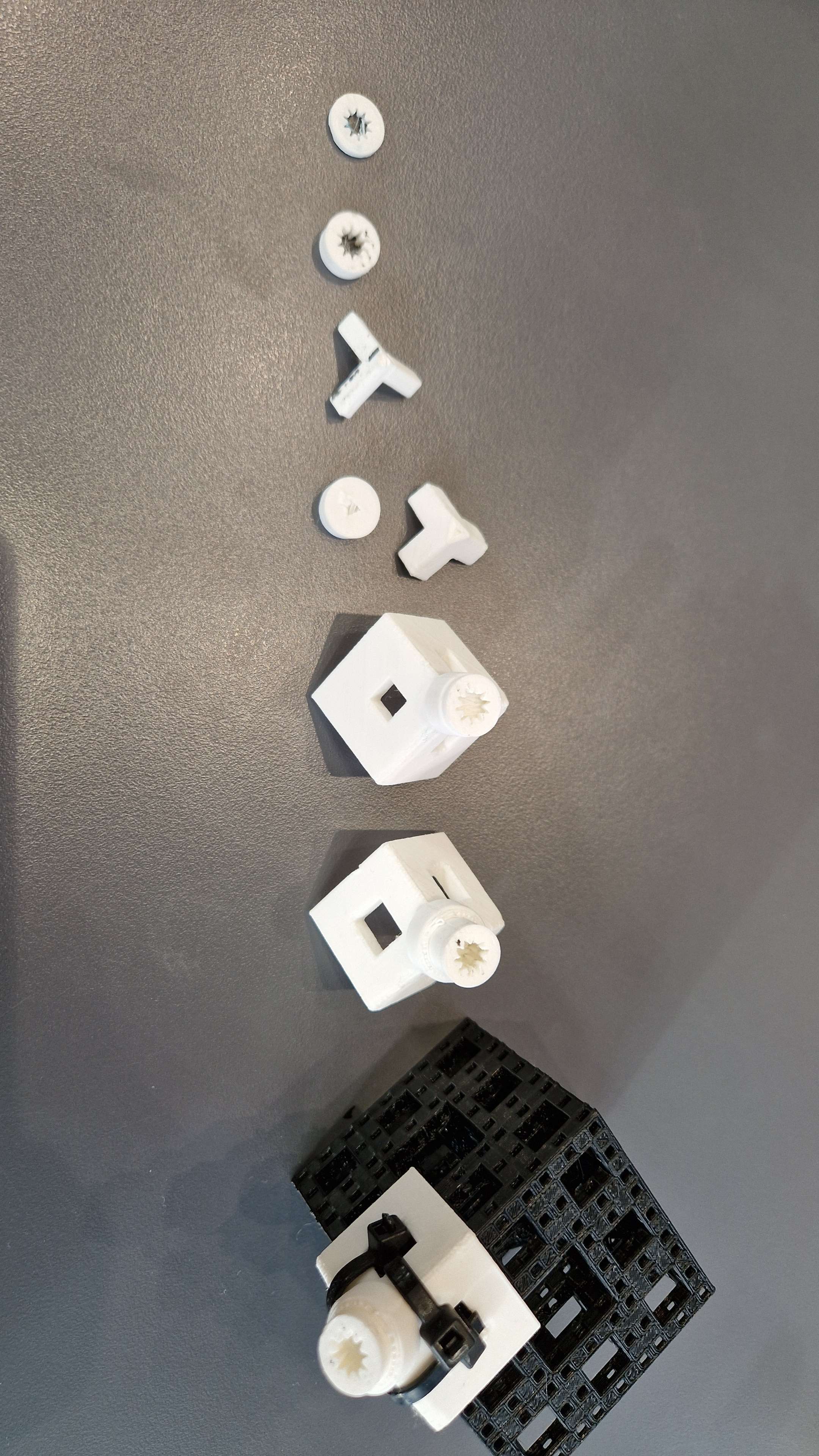
Image of the different design iterations of the motor shaft.
The first few iterations was focused on trying to create a part that fit onto the motor shaft. The shaft has a cog attached to the end which has 10 teeth. The design of this part proved to be a big challenge as i am still not sure how much spacing is required between the gear and the connecting piece. Spacing used in final versions is 0.4mm but i have had prints were i have had to use a knife to make the part fit, while other times it fit too loose. The depth of the connecting also ended having to be very precise.
The part that is supposed to hold the cube also went through multiple iterations. The connecting part to gear slots needed to have larger surface area to prevent the parts from disconnecting at high speed. Also the holder for the cube needs to be large enough to prevent the cube from flying out.
The cup for the cube also needed multiple iterations as the cube would fall out when rotating. In the end i ended up adding holes into the cup so as backup i could zip tie the cube in place.
ROTATION There also were problems with constructing the motor shaft in fusion360. Apparently rotating a cubic object to face pointy side up is not a 45degree rotation in 2 axis. The rotations i was told should work are x = 145, y = 0, z = 45 but i ended up with x=45, y=325, z=0. So the solution i came up with is just to add 90 to 55 until its correct. Mathematically it should be arctan(1/sqrt(2)) which is 35.264. 90-55 is 35, so if 55 does not work try 35.264.
Stand
Since the stand was going to be a pyramid, i started by constructing a square then using the “loft” function to raise it to a point above the square, this results in a pyramid. From then i began digging out space for the motor and arduino, as well as a hole for power supply.
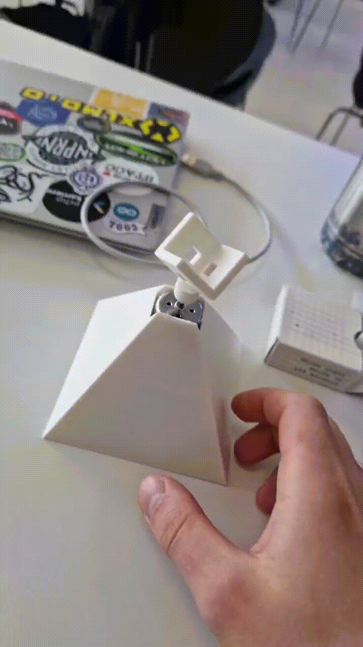
The inside of the pyramid is modeled so there are slopes lower than 45degrees, this is done to make the print easier. 3D-printers are not able to create large overhangs without support for the plastic, so some sort of support was needed.
Problems
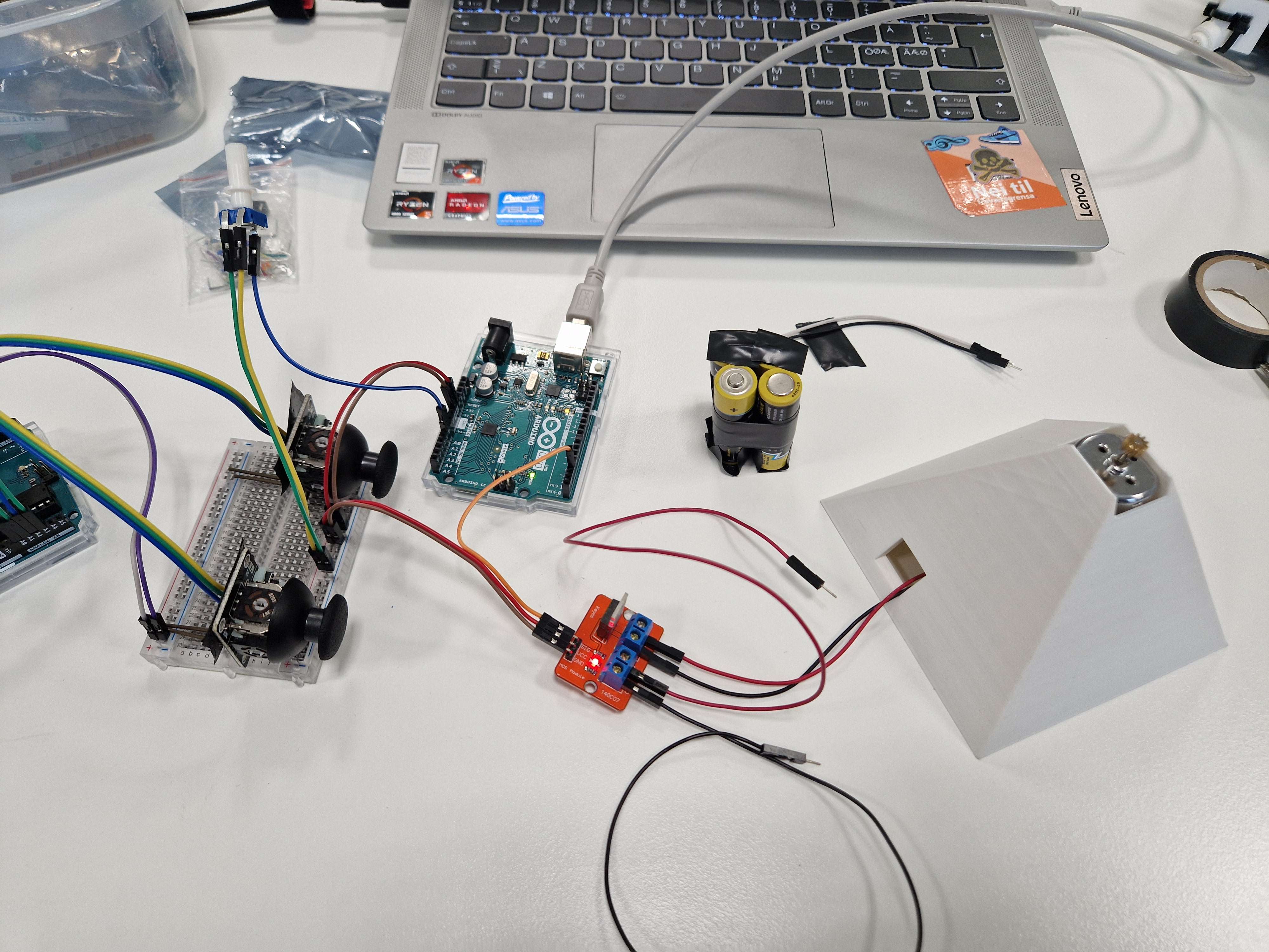
The main problems i have with the design so far is controlling the speed of the motor. An arduino has a 5v and a 3.3v output which i initially planned to use to power the motor, this ended up being too fast. I have tried 3 different methods so far to controll the speed.
Analog Arduino Output
The first attempt to control the motor speed was done by using arduino analog output pin. Using high values(close to 1024) the motor worked like normal(high speed). When using lower values the motor would emit a beeping noise and not rotate.
Voltage Divider
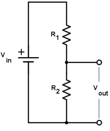
Since the motor was spinning too fast with 3.3v, an attemtp to reduce the voltage was made by construcing the circuit above. I was using 2 resistors of the same value, this would result in reducing the voltage by half. This also resulted in the motor emiting a noise and not rotating.
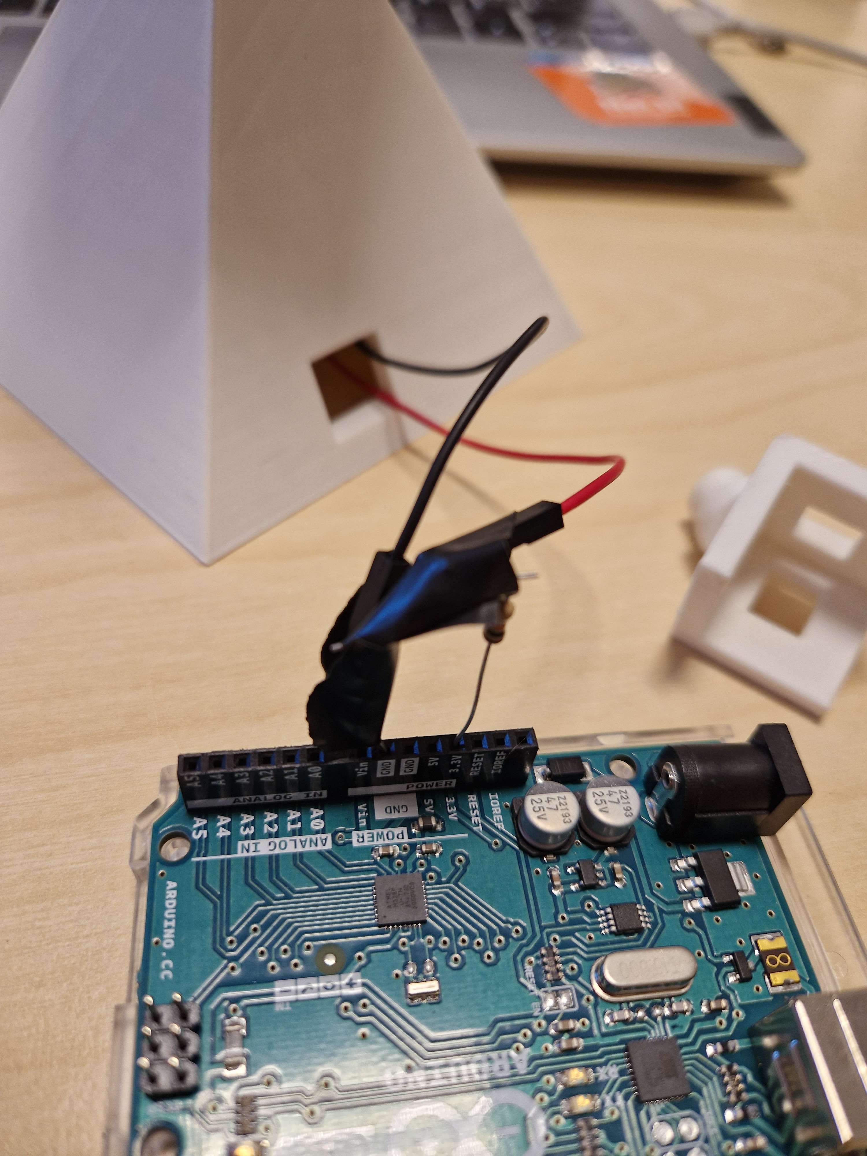
Image above is my attempt at construcing the circuit with electrical tape.
Motor controller
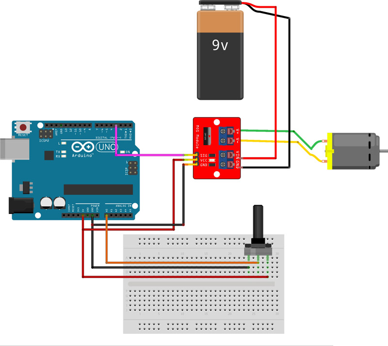
The circuit above aims to use a potentiometer to control the motor speed. I attempted to construct it by replacing the 9v power source with 4 1.5v batteries combined in series, which adds up to 6v. This kinda worked, it was able to reduce the speed of which to motor was spinning at, but it is still too fast for the intended use.