Assignment 05: Final Project - Prototype 1
List of content
Background
The goal for this assignment was to create a first prototype for the final project. The prototype should be used for testing and further development. The end goal i am working towards is to create a working quadcopter drone with auto stabilization. I decided to work towards completing the drone controller so i have something finalized i can use for further developing the drone. Last time i worked on the controller i ended up with a box were i could attach joysticks, and enough space to hide away electronics. Unfortunately there was not enough space because i did not do a good enough job in messuring how much space was needed. The design also did not account for me still using a breadboard for the electronics which also did not fit in the box.
The prototype needs to solve the following.
- Make space for radio transceiver, usb-type b powerplug for arduino, and electronics.
- Find a better solution for electronic wiring
Design process
Whilst trying to recalibrate drone motors a electronics teacher found interest in what i was doing and ended up helping me for almost an hour. Before he left i asked if he had any ideas how i would fit everything into the controller box and he told me to design a circuit board instead of using a breadboard. Designing circuit boards was originally planned for this course so this was the best opportunity i could get.
The main reason i had to use a breadboard is because the arduino is limited in ground and power connections, everything else has a direct wire from a component to the arduino. The breadboard is mainly used to help parallel connecting components with power. So the circuit board does not need to be complicated. The other reqirement is that it needs to take up less space. To do this i need to create an arduino shield, which from my understanding is just a circuit board that is placed on top of an arduino with some extra “stuff”.
KiCad, the program i am using for designing the circuit board has an arduino “symbol” which gives me a “schematic” “object” for the shield i am trying to build. It also have the same for the radio transceiver i am using. But it did not have “symbols” for the joysticks i am using.
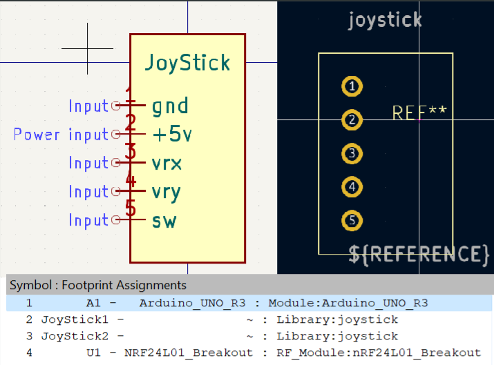
This next part i spent 5 hours on troubleshooting but i found out that i can create my own components. To do this i had to create a “symbol” and a “footprint”. A symbol is how the component is representet on schematic view, and footprint is how the compoentent is representet on PCB view. These also needs to be linked in footprint assignment if not the component does not exist in PCB view, which means that there is no physical model for the component.
The image below shows the schematic and PCB view of the joystick component, and the footprint assignment.
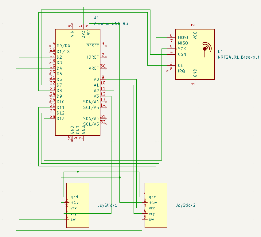
Otherwise, creating a schematic for the circuit board is easy once you have all the components placed down. For my level of complexity i just connect lines, but i imagine it could be more advanced later. Image below is how the results looked like.
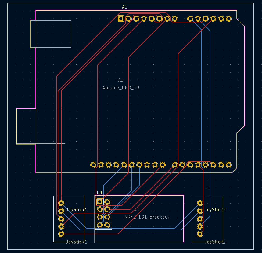
The main problem i had with creating the PCB for the circuit was that i did not know i had to select where the edge of the circuit board is. In hindsight this is sounds like a really obvious thing to do, but there was a 3D-view for the PCB which tricked my by showing me the circuit board with apparently imaginary cut out lines. I only found out about this problem when i got an email from the manufacturing site telling me my build failed because of “there is no Keepout layer (Board Outline)”. After multiple resubmissions and emails i figured out i just had to create a box around and put the box on “Edge.Cuts” layer. Image below is the PCB view of the circuit board.
When i received the circuit board i realized that the holes for the components i created were a different size than the others. The holes was too small but i found out i could use pins that was malleble enough to be forced through the holes. I then used an soldering iron to attach pins to the circuit board.
Now that i had working electronics i then needed to fit everything inside some sort of container. Since i already had a design i only needed to make small adjustments. I expanded the inside just enough so the circuit board does not jiggle inside. Created enough height inside for the wires. Made sure the powercord hole was in the right posistion. Created a hole for the radio transceiver. The image below is how the controller looks like in fusion 360.
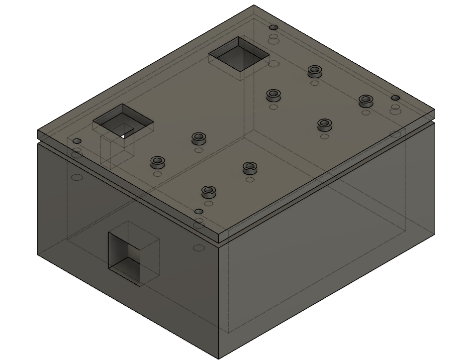
The underside of the joystick component is uneven with pins solderd on. Therefore i up creating support rings for the joysticks in hopes that it would be more even.
Result
The result i ended up with is a functional non-ergonomic joystick radio controller. Since the controller is programmable it could in reality be used for almost anything.
Discussion
I have previously experienced joystick value drift when testing the joysticks. Ideally i should have included a button that can be used to reset the joysticks, or a way to restart the controller. By experimenting with this prototype i should be able to determine if this is necessary.
When shaking the controller the only movable part is the radio transceiver. So i succeeded in making the box just small enough for the cicuit board, but i failed to lock the radio in place. I am still not sure what the best solution would be to solve this. I have shields for the radio, but there is still no good way to attach this to anything. I could always make a container thats an exact fit and then secure the box to something, but i think i am more inclined to try to solder the radio directly onto the board. The radio antena would stick awkwardly out the box either way.
The controller is not very ergonomic, and making smooth shapes is something i want to learn so this should be fixed. The easiest solution i see is to import the controller into blender and then create handles. Although this would work really well, i think i want to design handles i can attach and detach. My teacher has said multiple times that he want someone to experiment with organic shapes in fusion, so i might end up doing that.
Designing circuit boards and actually ordering and receiving them is a really cool thing and something i will continue doing in the future. My design process for electronics will now be to use a breadboard to design the circuit. When the circuit is complete, i will then order a circuit board to compress the circuit.
Next step for the final project
The next step for my final project is use the controller prototype to develop the drone. The drone has gyro and accelerometer which i have little to no experience with. I also need to design a circuit board and a container that protects electronics.
The goal is still to create a drone with auto stabilization, in order to code the stabilization i might have to develop a system to lock the drones axises so i am able to test stabilization in x and y axis separately.