Assignment 06: Input-Output
List of content
Background
The goal of this assignment is to use a microcontoller to read something from the world around us and to then use a microcontroller to interact with the very same world. My final project consists of a controller and a drone. The controller reads force? physical movement? in from of 2 joysticks. This has already been done so for this assignment this wont be the focus. The drone reads angular momentum and acceleration. This data will then be used in a self balancing algorithm that controls motor power. For now i just want som readable data and hopefully be able to turn on the motors with the use of the sensor.
Sensors
I wont be giving an in depth explanation of what a gyroscope is as the physics behind it is complicated and out of scope of this assignment. The only thing thats important is that a gyroscope conserves angular momentum given to it, whilst what we are using is an electrical gyroscope which measures angular momentum. For simplisity i will be refering to this as just gyro. The image below shows the axises a gyro measures angular momentum in.
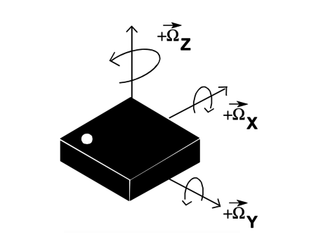
An accelerometer measures change in movement, think about what happens when you go from low speed to high speed in a car. You get pushed into the seat when the speed increases, but when you already are at high speed nothing happens. An acceloremeter does the same, but outputs an electrical signal according to the acceleration. Same as the gyro, this also measures in x,y, and z-axises.
//Accelerometer picture
Angular System
If a gyro measures angular momentum, how much change in rotation an object has, why do we need an accelerometer also? This is because a gyro is prone to drift over a long period of time. The accelerometer will account for this error.
The reason why we need both a gyro and an accelerometer is because both is inaccurate in its own way. A gyro provides accurate data in the short term but drift over longer time. An accelerometer provides accurate data over a long term, but is noisy in the short term. The goal is to combine the two to get accurate angular measurements. Which can be done with a complementary filter. A complementary filter is just a quicker approximation of kalman filter which is the proper way of combining accelerometer and gyro data.
Accelerometer formula for Y-axis:
\(\rho = arctan(\frac{A_x}{\sqrt{A_y^{2} + A_z^{2}}})\)
Accelerometer formula for X-axis:
\(\phi = arctan(\frac{A_y}{\sqrt{A_x^{2} + A_z^{2}}})\)
Complementary filter:
Filtered angle = $ \alpha $ * (gyro angle) + (1 - $ \alpha $) * (accelerometer angle)
\[\alpha = \frac{\tau}{\tau + \Delta t}\]
The gyro/accelerometer chip(MPU6050) is mounted on a breadboard. When i move the breadboard, change in rotation is calculated and plotted on the computer. Time is in x-axis whilst rotation is on the y-axis.
Result
When the breadboard is tilted forward, motors on the front side of the drone turns on. The more tilt the breadboard has the higher power is given to the motors. This also works for right/left and backwards. Right now tilt to power is a linear function which most likely will not be enough to stabilize the drone.
Discussion
-
Remember to keep in mind upper limit for voltage for electrical components. There is a reason a upper limit exists, and apparently it is to prevent it from getting destroyed. I got reminded of this when the MPU6050 chip stopped working. The voltage range for the chip is 2.375V-3.46V and i had been testing it with 5V. Meaning that most likely it got too hot and something got destroyed. The day before handing in this assignment i got a new chip and everything worked like it used to, confirming that the chip got destroyed.
-
The plan was to attach the sensor on a circuit board and then build and encasing to mount on the drone, but due to time constraints and me burning the sensor this has to wait. So for this demostration the sensor data is being sendt over radio to the drone, and then the motors turn on by 4 different variables for power. The stabilization is not quite done, as the angle to power is currently a linear function but it should most likely be exponential or something of a high degree. If not i imagine it could wobble back and forward and worst case not give enough power to be able to prevent it from flipping.
-
Reading sensor data from the ground up is actually really complicated. Everything comes in on off signals and you have to convert it into bits. Fortunately for me the open-source community is amazing and nearly everything i need already exists. I used someone else’s implementation to convert MPU6050 raw data to usable data saving me alot of time. However, doing this as an exercise in the future sounds like a good way to really gain in depth knowledge of how electrical components communicate.
-
What are the power requirements of my application? The two components in question are the input device(MPU6050) and output device(drone motors). The input device draws a low enough amount to be powered by an arduino, which is most likely going to draw more power storing and calculating angles, so the MPU6050 power requirements are negligible. The motors however draws around 2.4amps at 13.7 voltage, which should be 32.88 wats. A quick google search tells me that a non LED lightbulb used in most homes draws more. Nevertheless i still need a battery that is able to supply that amount of volt over a couple of minutes when i switch away from a stationary power supply.